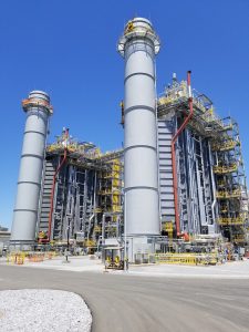
Facts and Durations demonstrating realized time and cost savings at WS Lee Steam Plant:
- All Durations are dependent on piping size and overall lengths.
- Closed Cooling: Total 19 days of cleaning -Cleaned 1st
- HMG Circulated the CC system 5 hours and checked the strainers which only showed a small handful of small particles.
- HMG Circulated the CC system for an additional 3 hours, inspection of the strainers showed less than a thimble of particles.
- The system was then put into services without incident.
- Condensate System: 8 days of total cleaning
- The Circulate pump tripped after 30 seconds, which was determined to be a motor fault.
This was corrected and the site ran 30 minutes, accepted and put into service.
- BFW Unit 11: Total 7 days of cleaning
- BFW Unit 12: Total 7 days of cleaning
- Cold Reheat: Total 7 days of cleaning
- Hot Reheat: Total of 6 days of cleaning
- Main Steam/HP Steam: Total 6 days of cleaning
- LP Steam System: Total 6 days of Cleaning
- Lube Oil Return: Total 8 Days of cleaning
Steam Blow Operations
The vast majority of the time and water saving for the steam blow came from the pre-cleaning of the steam piping by HMG prior to the start of the steam blow. In order to improve on the duration and water consumption of the steam blow, we reviewed and improved on the following:
GT Load
The initial design of the steam blow and temporary piping was performed by Fluor. During our engineering review, it was determined that the information and calculations that Fluor generated were highly conservative and excessive. These calculations resulted in higher GT operating loads and water consumption. Specifically, the flow model of the steam was calculated by using both Arrow program and a HRSG heat balance program. The heat balance program produced a fixed pressure drop across the superheater tube bundles that did not provide accurate results for the steam blow condition. This was corrected. Secondly, Fluor did not use the guaranteed case for the CFR calculations. They chose to evaluate all cases and determine the worst-case scenario themselves. Although this is not wrong, it is excessive. This was reviewed by us and discussed with the onsite team for Duke, Siemens and Vogt. This reduced the load of the GTs, process conditions but maintained within the allotted CFR conditions.
Time Reduction:
The Fluor process followed a very defined schedule of activities. They intended on performing the individual blows for each of the units as:
- HP -> Target
- CRH -> Target – Reverse
- HRH -> Target
- LP -> Target
This process was to be repeated for the second unit.
During the review of the procedure, we worked with Duke engineering to eliminate the CRH target blow as it has been Hydro Milled and will be targeted during the HRH blow. This saved a minimum 12-hour evolution.
During the steam blow of the HRH on the first unit, the HP CFR was also calculated and revealed that the CFR conditions were met. We worked with site personnel to perform the steam blow of the second unit all at one time. The sequence of the second unit blows was as follows:
- HP -> CRH -> HRH -> Target
- LP -> Target
Performing the HP/CRH/HRH all in one path, HMG saved between 20 and 40 hours of operation.
Based on the performance of the units during the individual blows, we worked with the site team to eliminate the CRH Combined back blows. The sequence of the combined blows was:
- HP -> Target
- CRH -> HRH -> Target
- LP -> Target
Calculations also revealed that during the individual blows, we achieved CFR conditions in the HP combined piping. HMG proposed to perform the HP -> CRH -> HRH -> all as one blow path. Having performed this exact blow path on both Siemens and Vogt equipment and with the approvals being awarded by individuals that Hydro Milling Group has worked closely with on previous projects. Engineering meetings and discussions prior to the start of the steam blow, during the engineering phase would have saved at least an 8-hour evolution following this parameter. In the Duke project, this would have equated to more days saved due to the GT and blow kit issues onsite.
Other engineering advancements that we made:
- HMG added a second silencer to reduce the back pressure. It was anticipated that 1 silencer produced 80psi back pressure at full load. We provided two at WS Lee which resulted in a back pressure of 20psi. This lowered the upstream pressure to allow for lower loads on the GT and lower steam flow conditions as the specific volume was less.
- We aggressively employed back flushing of the drip legs. This involved injecting condensate to all drip legs during operations to clear out debris. During the initial phases of the blow, only slightly discolored water flushed from the drip legs due to performing Hydro Milling prior to the steam blows. Our process of back flushing removed any remaining debris at the drip legs and clean clear condensate flowed out of the bottom. Note: Use of the plant drains or blow out the bottom was originally intended by Flour. This does not remove the bulk debris which can carry over into the steam system and foul the targets.
Further improvements to the overall project cost and details can be made if HMG handles the steam blow engineering in its entirety. Due to design issues, weeks of schedule was lost to blow kit issues leaking. The temporary steam pipe was not engineered to our spec. There is a difference between permanent plant designed piping and temporary piping. Both will meet B31.1 but the plant designed piping has a great longevity and costs are higher.
For the WS Lee project, we are confident that we could have engineered the piping to eliminate all need for chrome piping and chrome valves. We could have eliminated (1) large chrome valve entirely saving the project $100K. The stress issues on the temporary blow kits were clear due to the rigidity in the system. The temporary condensate system was excessive and costly. The seal steam and aux blow piping were excessive especially with a Siemens unit that allows for air blows of this system.
We now estimate that we could have saved upwards of $600K or more plus weeks of schedule by combining our methods of Engineering, Planning, Hydro Milling, and Steam blows if it was elected to allow us to engineer the steam blow system and tailor the overall Pre-Commissioning Services to the specific site needs. A Full-Service plan will net better results. These savings will more than cover the overall cost involved for the contracted services.
STEAM BLOW STATISTICS:
Steam blow schedule was increased due to noise restrictions during night time hours. Restrictions allowed to fire the GT’s between 6am and 10pm. After 2 ½ shifts it was deduced that the GT’s could be run at low rpm over night to avoid wear during stopping and firing daily. Thus 54.5 hours of the GT run time was low rpm night shift run time, not actual steam blow duration. Actual steam blow duration 77.5 hours total (6.5 shifts, 3 ¼ days due to Hydro Milling prior to Steam blow).
- Total GT run hours: 132 hours
- Unit 12 individual blows under load: 29 hours vs typical 150 to 200 hours
- Unit 11 individual blows under load: 31 hours vs typical 150 to 200 hours
- Combined LP under load: LP 10 hours
- Combined system under load: 7.5 hours
- Total Steam Blow duration: 77.5 hours (6.5 shifts or 3 ¼ days)
- Expected Demin water consumption: 9 Million gallons
- Actual Demin water consumption: 3.5 Million gallons
Prior to starting the Steam Blow, Working Closely with the Clients, Pre-Commissioning and Construction Teams, we wanted to look at other areas for possible time and cost savings. Taking into account lessons learned at previous projects the STG Lube Oil system can often run for days. It was proposed to Hydro Mill the Lube Oil Return followed by air blowing and drying process to remove moisture content to -40F. Hydro Milling the Return would result in no particulates contaminating the Supply Tank. For the Lube Oil Supply, we elected to apply a high velocity two phase flush utilizing a engineered TAP Flush Process. HMG have integrated exclusively, Elden Consulting and Industrial Services Technology to provide superior Specialized Industrial Cleaning, Commissioning and Pre-Commissioning Services with HMG being a full-Service provider.
TAP Flushing utilizes a formed air and water mixture that passes through the pipe system at high a velocity to remove loose mechanical debris, internal water-soluble coatings, loosely adhered welding slag, corrosion deposits and other foreign contaminants from the pipe surfaces. TAP Flush™ is chemical free and an effective replacement for conventional mechanical pigging and air blowing of piping systems. However, chemicals can be added to enhance the cleaning operation (e.g. degreasing agent) to achieve the desired result. The flush is performed by generating a pig of water that has been entrained with air to achieve a pig density that is nearly 30% that of water. This aerated water pig is displaced through the piping system at velocities of 20 to 40 feet per second.
The motive force for the pig is provided by compressed air held in air receivers at the TAP Flush™ entry point. The expulsion of this compressed air into the TAP Former™ vessel results in a low-pressure gradient throughout the piping system that forces the aerated pigs to the desired exit point. The intrinsic properties of the air/water mixture allow the pigs to pass through varying pipe geometries including pipe 90° elbows, tee runs, tee branches, valve bodies, and vertical lengths of pipe while maintaining the pig integrity.
This quick and effective two-phase flow process generates highly turbulent and flush velocities with minimal water consumption and no hazardous waste generation. Unlike air blow procedures, no exclusion zones are necessary. Full turbulent flow at the pipe wall caused by the two-phase (air/water) pigs generates Reynolds numbers of 4-5 million and typically requires a range of 5 to 10 pig passes to complete a flush path depending on the size and state of the system.
Once each system is deemed cleaned, it will be air dried using a compressor to a stable low dew point. At which time, the system will be closed to prevent contamination and moisture from entering the pipe.
By performing the TAP Flush to the Lube Oil Supply, we are able to remove a significant amount of Construction Debris down to the smallest Particulate Debris that would have caused a lengthy Lube Oil System Flush.
Duke Energy also elected to have HMG perform a Degreasing and Steam out of the Auxiliary Boiler to Satisfy the OEM requirements. Adding the Engineering of the Circulation path and set up to increase the efficiency of the Boiler Performance during operation as a fault preventative and time/cost saving Measure.


